Design Guidelines

send cleaner files and get cleaner quotes the first time

Following these guidelines helps your parts quote more accurately, reduces delays, and makes it easier to move straight into production.

1:1 ScaleExport at final size in mm
DXF PreferredCut geometry only
Closed PathsNo broken contours
Max 900 mmPer part in either direction
Quick Checklist
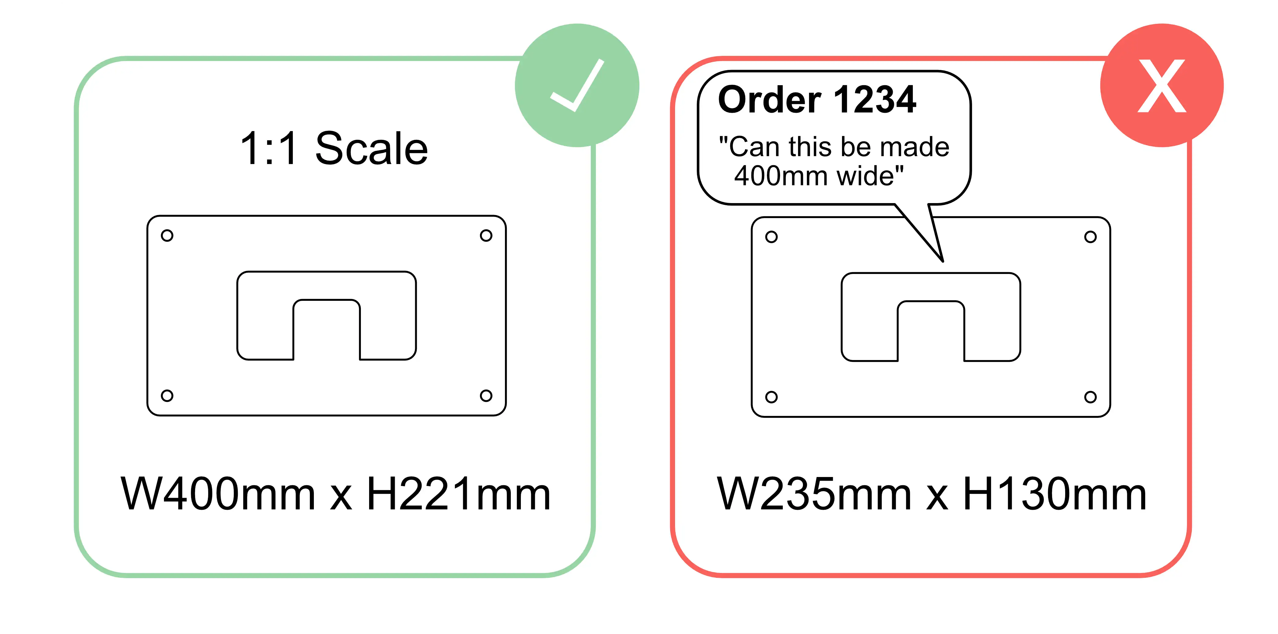
Draw in millimetres at full 1:1 scale
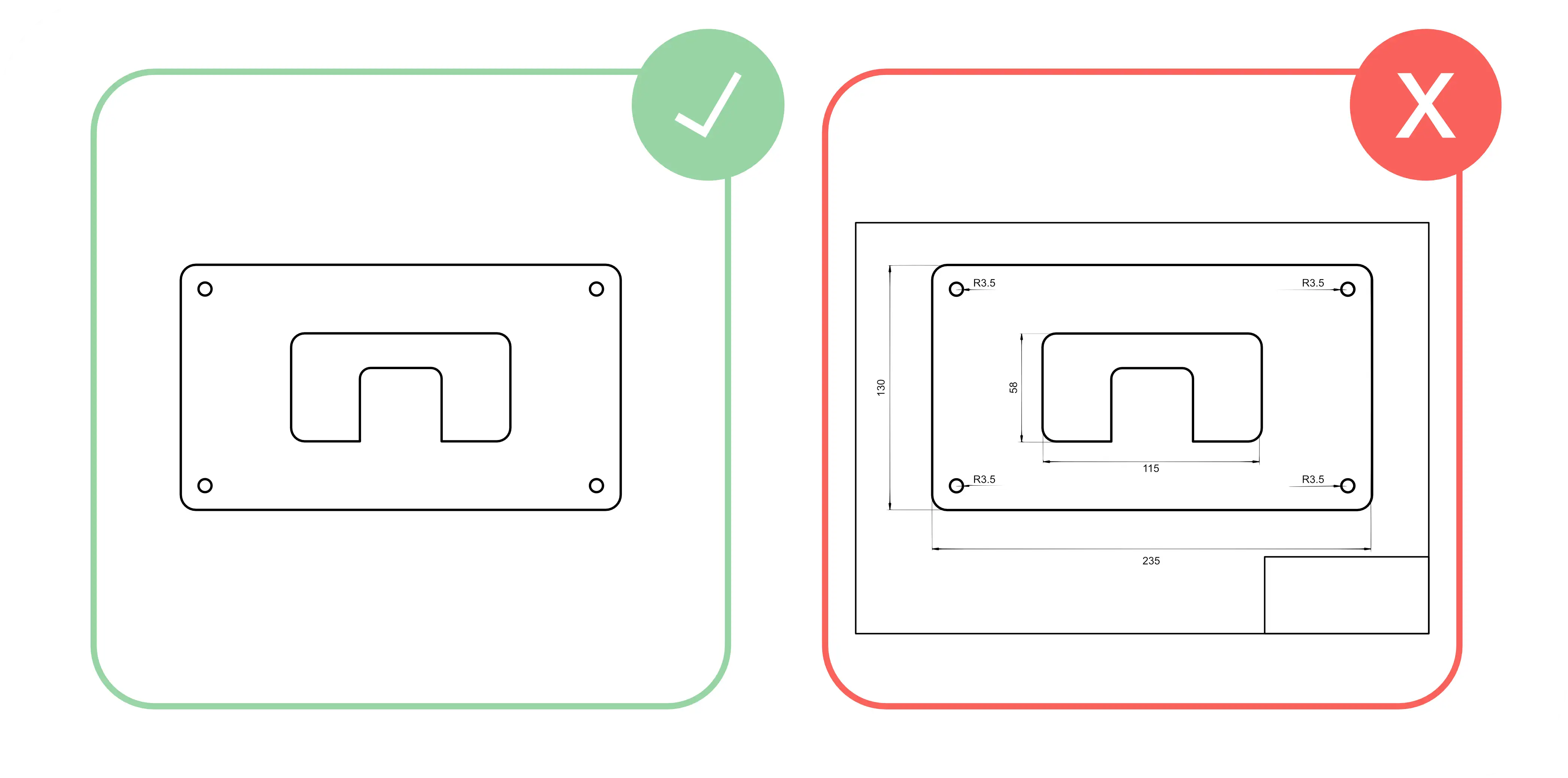
Keep only the part geometry and cut paths in the file
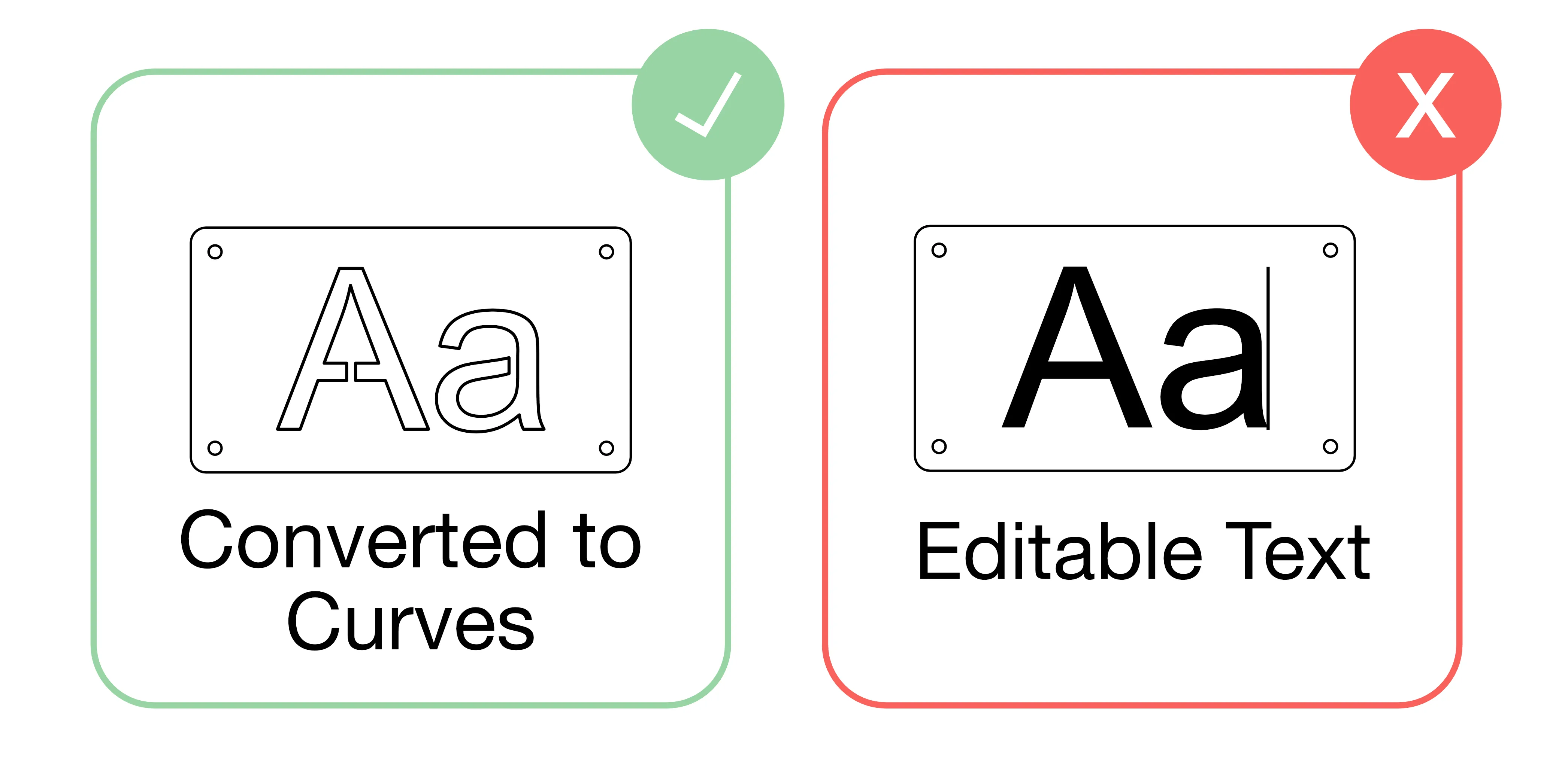
Convert text to outlines before exporting
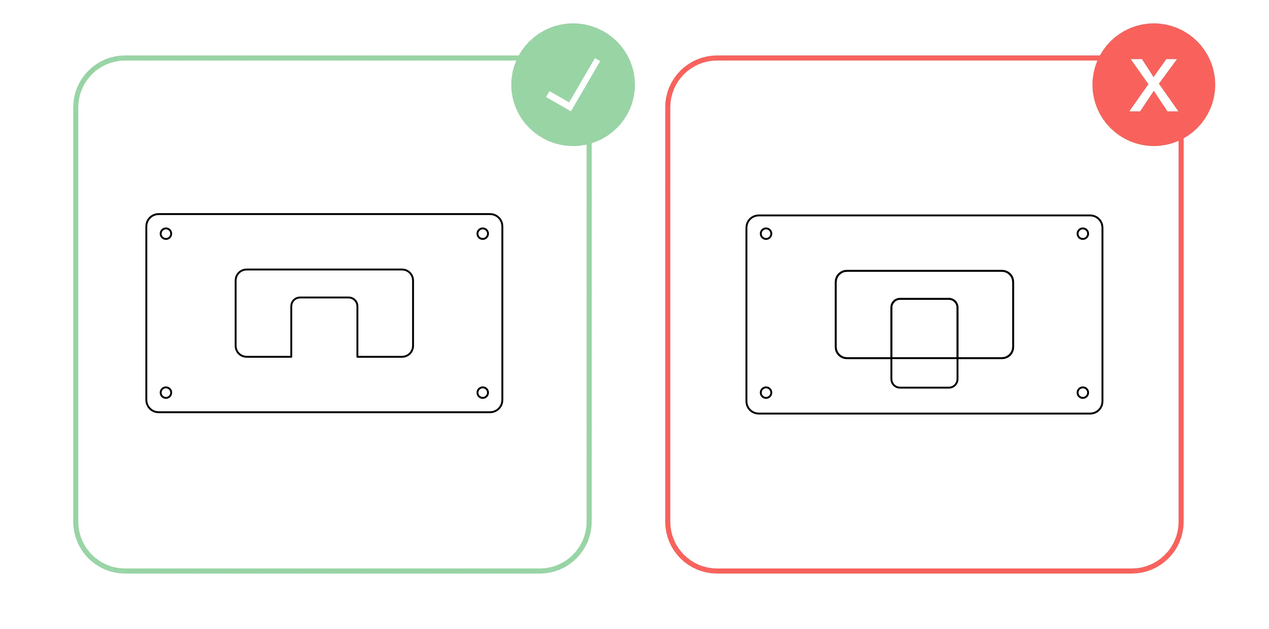
Add bridges to stencil-style text and enclosed islands
Avoid overlaps, duplicate lines, and open contours
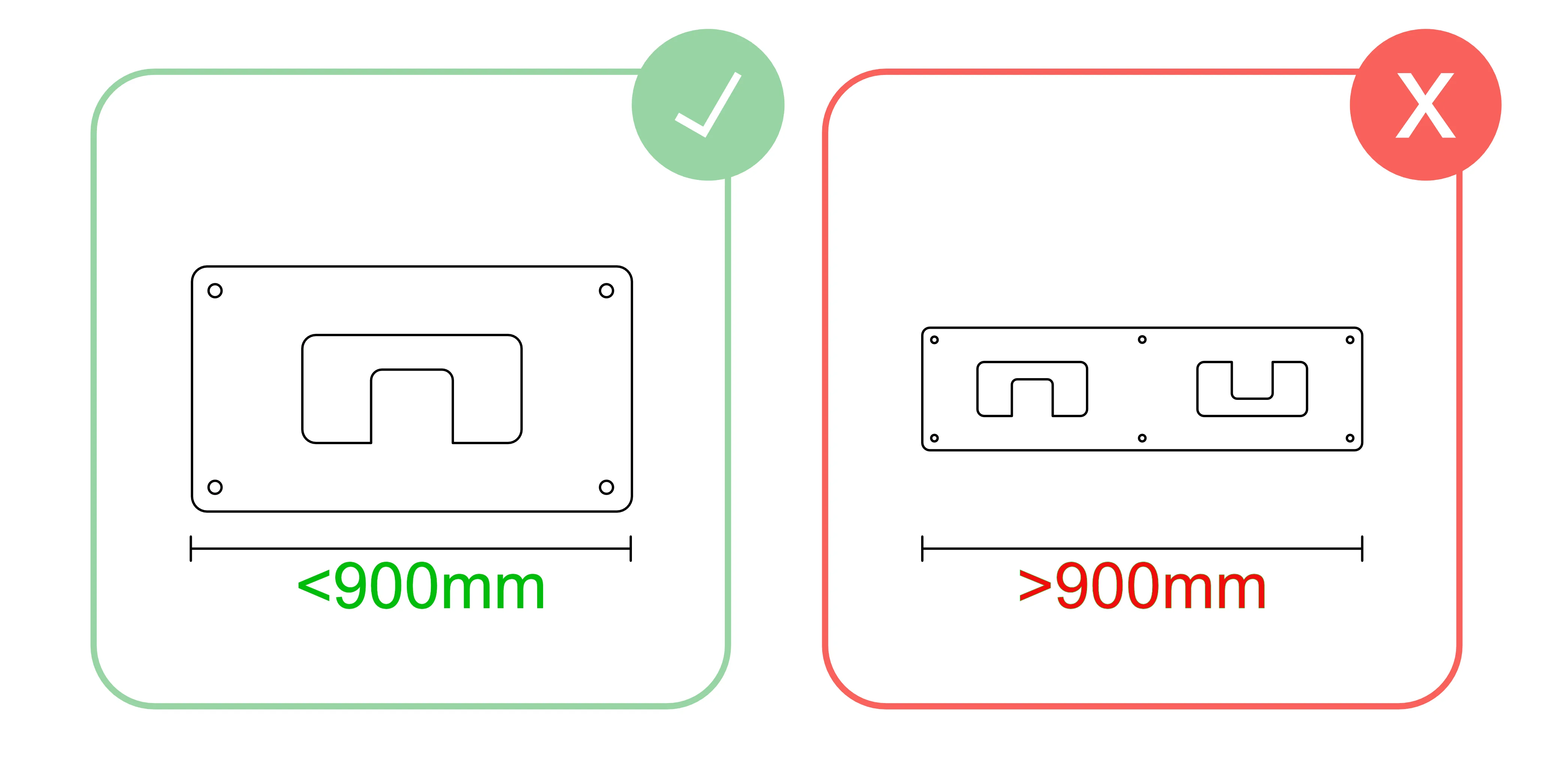
Keep parts within 900 × 900 mm
Why It Matters

good file preparation reduces delays before production starts

Most quoting problems come from scale issues, stray geometry, open paths, or features that are too small for the selected material. A cleaner drawing makes the price more reliable and reduces manual checking.

Scale artwork to 1 to 1
Rule 1

scale artwork to 1:1

Send the drawing at the exact size you want it cut. Work in millimetres and export at full size. Written notes asking for a different size can cause confusion if the geometry itself is not scaled correctly.

Check your document units are set to mm before exporting.
Print at 100% or measure a known feature if you want a quick sanity check.
If the drawing is not at final size, fix the geometry before upload rather than adding a note.
Include only parts and cut paths
Rule 2

include only the part and its cut paths

Remove dimensions, title blocks, notes, page borders, and any other non-cutting information. The file should contain only the geometry that needs to be cut or engraved.

Delete any hidden objects, spare sketches, or duplicated parts left elsewhere in the drawing.
Keep each file focused on one part or one intended grouped assembly.
Use sensible filenames so your parts are easier to identify later.
Convert text to outlines
Rule 3

convert text to outlines or curves

Editable text should not be left in the cutting file. Convert it to shapes first so the geometry stays exactly as intended and does not rely on missing fonts or software substitutions.

In CAD or vector software this may be called outline, expand, explode, or convert to curves.
Do this before export so the quote reflects the actual geometry rather than a font dependency.
Stencilise fonts and shapes
Rule 4

add bridges to stencil-style text and internal islands

Enclosed shapes will fall out unless they are connected back to the main part. If you want letters or islands to remain attached, add bridges so the finished part stays in one piece.

Letters such as A, O, P, R, and enclosed logos usually need bridges.
Place bridges where they look deliberate and are wide enough for the chosen material.
If you want a fully cut-out centre section, no bridge is needed.
Small holes and cutouts
Rule 5

size holes and small cutouts correctly

Very small internal features may not cut cleanly. As a practical rule, holes and cutouts should be at least 50% of the material thickness, and no smaller than the process can produce reliably. Typical cutting tolerance is around 0.2 mm, so hole sizes should be designed with enough clearance for the intended fit.

Example: in 3 mm material, a reliable minimum hole is usually around 1.5 mm.
Tighter features may need checking or a design adjustment before production.
If a hole needs to accept a bolt, make sure it is sized with enough clearance for the bolt to pass through comfortably.
Avoid intersecting or common lines
Rule 6

avoid intersecting, overlapping, or common lines

Overlapping geometry can create double cuts, uncertain paths, or quoting errors. Keep the drawing tidy so each cut path exists once and the intended shape is obvious.

Delete duplicate entities before export.
Trim intersections properly rather than leaving crossing lines in place.
If separate parts are meant to be separate, do not let their geometry overlap.
Close open contours
Rule 7

remove open contours and broken lines

Closed geometry is much easier to quote and manufacture reliably. Small gaps, unjoined endpoints, or broken contour segments can prevent a file from behaving like a proper closed part profile.

Join endpoints and close small gaps before exporting.
Use proper arcs and circles where possible rather than fragmented line segments.
Delete floating fragments that are not part of the final part.
Maximum part size
Rule 8

keep parts within 900 × 900 mm

The maximum online part size is 900 mm by 900 mm. Larger parts should be discussed before quoting so handling, material availability, and delivery can be checked properly.

Measure the largest overall width and height of the part, not just the main body.
If a part is too large, splitting it into sections may be a better option.
FAQs

common questions before upload

What file type should I send?

DXF is the preferred format for online quoting. Keep the file clean and exported at full size in millimetres.

Can I include notes in the file?

No. Remove notes, dimensions, title blocks, and page borders. Only include the actual part geometry and any intended cut or engrave paths.

What if my file does not meet the guidelines?

The file may need checking or adjustment before it can be ordered. Cleaner files usually lead to faster, smoother ordering.

What are micro joints, and why might I see a small tab on my part?

Micro joints are small tabs deliberately left during laser cutting to help keep parts secure in the sheet while they are being cut and handled. They reduce the chance of smaller parts tipping, moving, or catching during processing, so a small tab can sometimes be visible on the finished part.

Can I still ask for help with a difficult file?

Yes. If the drawing is unusual, oversized, or you are unsure whether it is suitable, get in touch before ordering and we can advise.

Need material information?

Check the available materials, thicknesses, and finishes before uploading a new job.

Ready to upload a file?

If your drawing is clean and sized correctly, move straight into quoting.